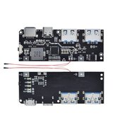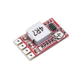
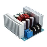
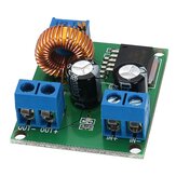
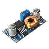
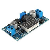
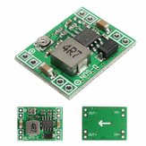
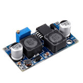
MPPT 5A napelem panel szabályozó akkumulátor töltő 9V 12V 24V automata váltással
US$10.99
A felülvizsgálat egy részét automatikusan lefordították.
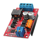
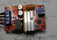
Jó termék, de nem szállít 5A töltőáramot, hacsak nincs megfelelő hűtőborda a két diódán és a két mofeten. Ez annak is lehet köszönhető, hogy az RCS nagyobb, mint 0,04,. Mindenesetre a meglévő hűtőborda nincs megfelelően az alkatrészek aláragasztva, mivel csak részben érinti a fűtött részeket. Még rosszabb, a fém hűtőborda megérinti a csapok néhány más alkatrészek, és fennáll a veszélye a rövidnadrág és a sérülés. Továbbá, az én egységemben, a kettős led forrasztják a másik irányba, és ennek eredményeként, amikor tölt egy akkumulátort, a kék led bekapcsol, és amikor az akkumulátor megtelik, a piros led jön. Mindazonáltal, ez egy jó mpt töltő. Csatolom a töltés profilt és annak diagramját, a KN3722 adatlapból.


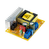
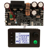
This device works quite well at lower currents (< 3A). MPPT via panel voltage tracking seems to work quite well. I have mine outputting an almost consistant 10 Watts(2.8A @ 3.6v) into a 1s20p Lithium battery(nom. 3.6v, 45Ah) from a 12.5 Watt panel (21Voc, 17Vmp), so approx. 80% efficiency, even in 42 degree celcius ambient heat with panel temperature above 60 deg C !! (Australian summer). In 'cooler' summer weather (mid 20's) I get maybe an extra Watt out at mid day (~11W -ish). Although this is advertised as working up to 5A, even after extensive testing I was not able to get much above 4A with a 25Watt(measured) panel and very good heatsinking: I only get 15 Watts out (4.2A@3.6v) so efficiency at higher currents suffers badly (25W in, 15W out = ~60% efficiency) This item, as shipped, will NOT work with 1S lithium because the regulation voltage can only be adjusted down to ~6.5v, however, it is relatively easy to modify it for 1S operation. To do this, simply replace the 22k resistor (R7, marked 223, 0603 size) with something around 75k to 100k. I used an 82k resistor which alows me to adjust regulation from ~3.0v to ~9v. Note that the supplied heatsink itself is okay, but it is useless as supplied because it is mounted with a thick dob of silicone adhesive. This is because A) the current sense shunt resistor is thru-hole and protrudes, and B) the PCB tracks under it have exposed solder pads. Poor design/lack of forethought by whoever did the PCB layout!. Therefore, mounting the heatsink directly to the PCB would cause a short circuit. I have modified mine with heatsinks on the top side packages(Mosfets and Diodes), and also a heatsink with a drilled hole (to clear the shunt solder pad) un the underside using double-sided tape as insulation to avoid shorts with the board tracks. Not exactly ideal, but much better than as-supplied.
This is a buck only converter so the solar side voltage has to build up. Good product. Not really power point tracking, because the power point has to be set manually. Otherwise, good.
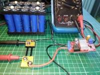
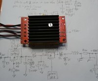
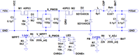
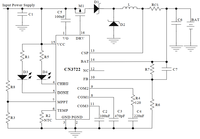
A testület körülbelül egy hónap múlva érkezik Romániába a CN-ből. A CN3722-es MPPT-szabályozó jól működik. Javaslom, mint a legolcsóbb MPPT, amit találtam (kb. 9 USD); működése állandó bemeneti feszültségen alapul (MPPT feszültség). Úgy is használható, ahogy van, de én inkább módosítani a hűtőborda, mert ez a veszélye az elektromos érintkezés, a szigetelés a hűtőborda fekete festék csak; Csináltam egy 3 mm-es lyukat a földi csatlakozás alatt D1 és tettem egy további hűtőbordát a PMOS és a diódák tetejére - csatlakoztassa őket egy 3 mm-es csavarral (1. és 2) fotó) - az eredeti hűtőborda alatt, amit kapton szalaggal és hőpasztával használtam. A sematikus a tábla látható a 3. ábrán a pin nevek vett a CN3722 adatlap (tipikus áramkör - fotó 4). A beállítás elvégezhető közvetlenül a napelem (SP) - állítsa be a V_MPPT-t arra a pontra, ahol a LED-ek villognak akkumulátor nélkül; ebben a pontban 1,04V (jellemző) az MPPT terminálon, R5 felett; a V_MPPT az SP jellemzői alapján is beállíthatja a maximális teljesítményfeszültségre (körülbelül 15..20%-kal kevesebb, mint a nyílt áramköri feszültség) egy további forrás segítségével (amelynek az áramerőssége 1A-nál kisebb) a kívánt feszültségre illeszkedik. (állítsa be, hogy 1.04V több mint R5 és / vagy a LED villogási pont, akkumulátor nélkül). Az akkumulátor csatlakoztatva beállíthatja a vég töltési feszültséget arra a pontra, ahol 2.416V (tipikus) az FB csapra - R7 felett, VAGY, ha az akkumulátor eléri a végtöltési feszültséget arra a pontra állítsa be, ahol a LED-ek megváltoztatják a színt - kékről pirosra (homályos) az én esetemben - kék töltődik, piros a töltés vége (az én esetemben - általában az egyik elvárja a piros töltés...). Kipróbáltam a panelt alacsony fény egy felhős napon (w/o hűtőborda) egy 100W 22V napelem, mintegy 20%-kal több energiát kapok az XMUND XD-PS1 erőmű MPPT-jéhez képest. Egy napsütéses napon is kipróbálom (melegítővel most) és hozzáadok hozzá egy megjegyzést.
2023. július 22-én, 2023. augusztus 6-án érkezett megrendelés. De az építkezés minőségének javítania kell... Melegítés a hátsó oldalon érintkező más alkatrészek, ami vezethet rövidzárlat és meghibásodás a készülék,


A termék törött volt, és halott volt. A tekercs elszakadt a szállítás során, mivel csak egy vékony műanyag zsák volt, és nem volt védelem. Azt hiszem, ez egy jó termék, amikor működik...


Szállításkor eltört. Rosszul csomagolt csomagolóanyag nélkül nehezebb csomag (Epever mppt napelemes töltő). Tehát egy tekercs eltört, miközben a csomagot elkerülhetetlenül kezelték.


Rendelt MPPT 5A napelemes szabályozó vezérlő akkumulátor töltés 9V 12V 24V automatikus kapcsoló 2 db érkezett a megállapodás szerint egy kis késés, de minden rendben. Ajánlom a vásárlást!


Nagyon jó termék. Gyors szállítás.


Gyors szállítás Görögországba. Nagyon jó csomag.


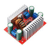
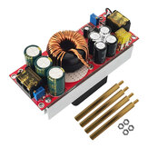
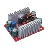
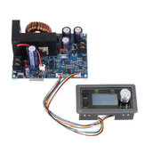
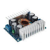
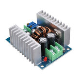
Geekcreit® 400W DC-DC Nagy Teljesítményű Állandó Feszültségáram Fokozó Tápegység Modul

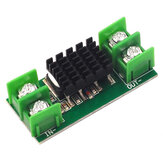
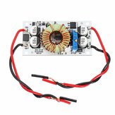
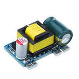
Konstans áramú, napelemes ideális ellenáramú dióda, akkumulátortöltő ellenáramvédő modul
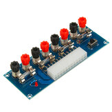
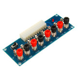
Geekcreit® XH-M229 Asztali Számítógép Tápegység Modul ATX Átalakító Tábla Táp Kimenet Modul


DC-DC tápegység modul 12V-ról 3.3V/5V/12V többszörös kimeneti feszültségkonverzióval
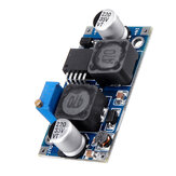
LM2596 DC-DC Feszültségszabályozó Állítható Léptető Feszültségellátó modul kijelzővel
5 db LM2596 DC-DC Feszültségszabályozó Állítható leosztás Leeresztő tápegység modul kijelzővel
3 db LM2596 DC-DC Feszültségszabályozó Állítható Lépjen le Tápegység Modul Kijelzővel
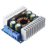
22A/1400W Buck DC Állítható Feszültség Szabályozó Feszültségállandó állandó árammodul

Geekcreit® 5A XL4005 DC-DC Átalakító Modul Állítható Lépéslejtő Tápegység
3db XH-M229 Asztali számítógép ház tápegység modul ATX átviteli panel Tápegység kimeneti modul
10 darab LM2596 DC-DC feszültségszabályozó állítható léptetéssel tápegység modul kijelzővel
Type-C PD QC AFC Gyors Töltés Hüllő Berendezés 5V 9V 12V 15V 20V Kimenet Töltő

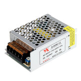
2db AC 100-240V egyenáramú 12V 5A 60W átalakító tápellátás vezérlő adapter LED szalagfényhez
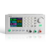
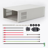
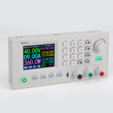
RIDEN® AC110V/220V - DC 68V 1200W szabályozott váltóáramú tápegység RD6018-hoz
20 db Mini MP1584EN DC-DC BUCK Átalakító Modul 4.5V-28V Bemenet 0.8V-20V Kimenet
12A beállítható Buck modul járművekhez, magas hatékonyságú, alacsony zajszintű, 95%-os hatékonyság

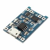
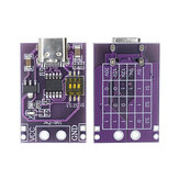
USB-lítium-akkumulátor-töltőmodul táplálási és védelmi integrációs lap
AC110V/220V átalakító a DC12V 20A 250W-hoz ventilátorral 200*110*50mm
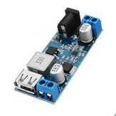
24V / 12V Átalakító 5V 5A DC-DC Buck Teljesítménymodul Lépés Léc
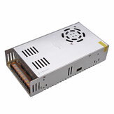
AC110V/220V átalakító a DC24V 20A 500W váltóáramú tápegységhez
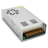
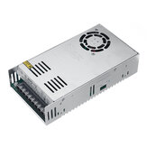
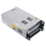
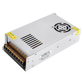
Geekcreit® AC 110-240V bemenet DC 24V 17A 400W kapcsolóüzemű tápegység vezérlő lap