Minden üzenet

Johnny_B_Goode 27/01/2022
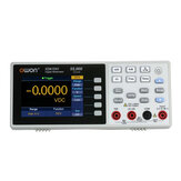
The bench meter arrived just 8 days after I'd placed the order. The meter and its accessories are nicely packed into a stout cardboard flip lid box. I used a Siglent SDM3065X to verify its published specifications. Its energy consumption measured just under 1W at the 0% backlight setting with just over 1W at 25%, & a max of 1.5W at the 100% setting. If like me, you've been using a handheld DMM to observe, for example, the variations in EFC voltage readings in a GPSDO over hours long periods each day, this low power demand will be welcome news. Not only do you avoid having to replace batteries once every month or so but the annual electricity costs will also be less than a year's supply of the the AAA cells required to abuse a DMM with such an onerous task, even if you never put it into standby mode (250mW) with the soft on/off button (no actual mains voltage switch). Whilst the measurement update rates are acceptable in this class of meter, unfortunately, capacitance measurements leave much to be desired. Not only does it refuse to report values < 0.5nF, measurement times are quite slow, becoming somewhat glacial on the 5 to 55mF range. Most cheap handheld DMMs can do a much better job of measuring capacitors. I chose the European mains lead (there was no UK option). I have a small stock of UK mains leads and an ample supply of 13A plugtops to convert 'foreign' mains leads if needed. The supplied test leads seem to be good quality. However, the same isn't true of the crocodile clip adaptors. Despite those deserved criticisms, this handy little bench meter still provides a very nice and cost effective upgrade over the cheap "9999 counts" handheld DMM I'd been using for long term monitoring tasks, neatly avoiding in my case, the need to replace sets of AAA cells on a monthly basis. I paid just under £100 for mine, which imho, is excellent value for such an accurate and compact 55,000 counts bench meter. IOW, I couldn't be more pleased with my purchase. :)
7
Ajánlások
Hozzászólások (0)
Johnny_B_Goode 09/02/2022
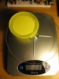
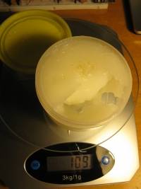
This pack of five test cables arrived on time and are just as good quality as a previous set bought about a year ago but with one important caveat as per the first set, namely that both sets are misdescribed as "silicone" insulated test leads. A simple test with a temperature controlled soldering iron (KSGER T12 set to 150 deg C) applied to the "silicone insulation" will actually melt said insulation if left in contact for more than a few seconds. Repeating this test against the silicone insulated soldering iron cord by way of a sanity check leaves no impression even at 200 deg C when firmly pressed into contact for over ten seconds. Other than the misleading description, the quality in all other respects is excellent. There are small differences between the previous sample and this one. The previous sample weighs in at 207gm (in the feather light cellophane packet I'd used to hold it in place on the scales), has croc clips with a tapered nose, the banana plugs have a low but sufficient tension in 4mm banana sockets and each lead measured within 5% of 18 milli ohms resistance. This later set of leads weighs in at 213gm, the croc clips are bull nosed, the banana plugs provide a noticeably higher tension force in the same 4mm banana sockets and the lead resistance is slightly higher at 21 milli ohms (+/-5%) - an insignificant increase. Even allowing that they don't have the implied resistance against contact with high temperature sources of heat, they're still an excellent value purchase. Note to BangGood marketing: please remove the erroneous implication in the product description that it uses a heat resistant silicone insulation material when a simple test readily reveals that this is far from the truth.
2
Ajánlások
Hozzászólások (0)
Johnny_B_Goode 30/06/2020
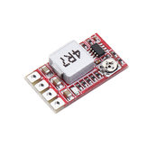
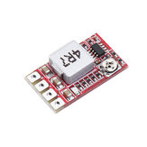
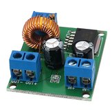
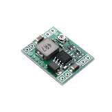
This is the tougher cousin to the 1.3A (1.2MHz switching) version. Whilst the voltage adjustment pot seems to be of reasonable quality compared to the crap ones used on the "Geekcreit® Mini DC-DC Converter Step Down Module" (and its clones), unless you need an in between oddball voltage setting (6 or 7.5 volts for example) and have the patience to finesse it onto the required voltage setting - it's very touchy, you'd be better off cutting the trace (at its necked point) which bridges the Adj option solder blob link (you can still blob this link if you need to restore the Adj option) and solder blob the required standard voltage option link. Cutting the Adj option bridging link so you can choose a fixed voltage setting is a safer option - no risk of the trimpot falling apart or going open circuit to over-volt whatever 3.3 or 5 volt rail you're powering with just one volt short of whatever the input supply voltage happens to be (12 to 24 volts perhaps?). Testing the fixed 5v option gave me a tad less than 5 volt (4.95 something volts). Ideally, I wanted a voltage between 5.2 and 5.3 volts so tried blobbing both the 9 and 12 volt option bridges instead which gave me 5.31 volts - right on the money as far as I was concerned. :-) These "3A" versions run a lot cooler compared to the "1.3A" version when testing with a one amp load so should be more robust than their 'weaker cousins' whose overheating/overloading protection seems somewhat lacking since I manage to make a 1.3A one start emitting its magic smoke due to a 5v CMOS RRO dual opamp shorting out the 5v supply rail in a Mark II version of a DIY GPSDO I had been testing (most likely a design error on my part, now since remedied). The specs mention 20mV of ripple noise which will be the RMS value. The peak to peak value will be approximately three times this value, circa 60mV p2p which is quite good and easily reduced to less than 10mV p2p with additional filtering if needed. JBG
5
Ajánlások
Hozzászólások (0)

Q: Does this Aferiy P210 work off 240 volt mains supply voltages used here in the UK?

Kérdezte Johnny_B_Goode tovább 2023-11-05 12:01:05

The seller Dear, thank you for your support. Our British warehouse is equipped with UK plug and the voltage is 220V~240V 50Hz/60Hz. And here is the manual:http://myosuploads3.banggood.com/products/20231030/20231030010535AF-P210V1.0120221212.pdf?_gl=1*1jcqwcd*_ga*NjQwNDc3ODc1LjE2OTg4MTkzMTc.*_ga_Z150VP5X0J*MTY5OTMxOTQzMS4yMi4xLjE2OTkzMjk0MjQuNTIuMC4w

2023-11-06 09:57:22 Hasznos (1)
Beküldés
Válaszok (1)
Johnny_B_Goode 17/11/2019
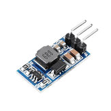
It turns out that the absent trimpot (the "adj" jumper bridge option) has been replaced with a 39KR, exactly the same value connected to the 5v option link which makes it preset to 5v without the need to solder blob any of the voltage option links. I found this out the hard way two days ago when I'd finally gotten round to using it in my DIY GPSDO project. If you remove this "excess baggage", solder blobbing the relevant voltage option links will now produce the indicated voltages. I also discovered, after turfing out the redundent 39KR from the trimpot location (it already has one in the 5v location!), you could combine the 9 and 12 options to get within a tenth of a volt of the 5v setting which might prove handy if this works out a little higher than the 5v link gives - I was getting 5.05v using the 5v link (or leaving them all open with the surplus resistor still in place) and, just 15mV more using the 9 and 12 volt links together instead - not quite a good enough improvement, I was looking to get 5.15 to 5.25 volts so used a 1K5R smd resistor to bridge the 5v link which got me a voltage of 5.216 open circuit and 5.17 on a 1A test load. Obviously, you can use variations on this idea to fine tune the voltage setting. Unfortunately, I managed to burn out the very tiny converter IC with the slip of a DMM probe so I'm now back to the other converter module I'd bought at the same time from BG way back last August :-( It's so sad because that was a really crap version of the one I thought I'd be getting going from the product pictured. The one, as pictured is probably ok but the one I got (not this module, I hasten to add) was so bad, I have to regard it as a "Fake version" in need of some remedial attention to get it to function properly (the Shottky diode was left disconnected from the inductor - a solder bridge needed to be closed and the crappy trimpot had to be slung in favour of a fixed value 33KR resistor to avoid the over-volting risk it had represented).
4
Ajánlások
Hozzászólások (0)
Johnny_B_Goode 14/08/2022
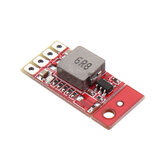
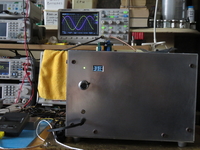
Bought 3 & tested 1. At first I thought it wasn't working properly until I noticed the current limit lamp on my cheap 'n' cheerful (it gets the job done but can't indicate the current limit setting like its more expensive cousins) LW-K3010D bench power supply was lighting up - I'd simply forgotten I'd set it to just over 0.5A for a previous test. /slaps head/ At 1.6A load, the inductor runs hotter than the IC but since this is powering an LPRO 101 rubidium oscillator, the current demand drops down to half an amp after two or three minutes and everything runs much cooler thereafter. The voltage varied by a few millivolts with temperature during my tests but this is a vast improvement over the hundreds of mV variation between the three 19v laptop chargers I've tested my rubidium frequency reference with and will allow me to pick any one as a power source without upsetting its micro Hertz accuracy. Up to now, I've been using the 19 volt directly to power the LPRO (dc input rating of 19 to 32 volts with 24 volts being the nominal recommendation). I'll be setting this boost converter to output 22 volts which will allow me to standardise on these cheap and ubiquitous laptop chargers for not just this one project but all of my other DIY frequency standards. I'd decided very early on to keep the mains PSUs out of my frequency reference enclosures to minimise thermal issues and the down time to repair them in the event of a psu failure (they run 24/7). Fixing such failures is now simplified to merely swapping out the dead wallwart or laptop charging brick with another good unit taken from my plentiful stock of spares. The attached image show the boost module parked on top of my Rubidium oscillator (RFS) with the scope behind showing just over 16 hours of infinite persistence recording the RFS phase shifting relative to my GPSDO (which as its own 6ns pk-pk disciplining wobble). Please note the unusually high ambient temperature for the UK (36.16 is the base plate).
0
Ajánlások
Hozzászólások (0)
Johnny_B_Goode 17/11/2019
The module that was shipped out to me, although physically similar in layout, used a similar 8 pin (but umarked and with a different pin out) to the MP1584 shown in the product photos. The trimpot was faulty, causing great difficulty in setting the output to 5.15 volts and prone to generating excessive voltage at random points of the adjustment range. I replaced the trimpot with a 33KR smd resistor and added a 200KR across the 6K2R smd resistor between ground and the Vref pin to trim it to 5.2v. Having modified it to give a reliable 5.2v output, I then discovered that it had excessive ripple, 400mVp-p no load rising to 800mV or more with a 1A test load. I gave up on this module and tried another one which had option solder bridge jumper links for 3.3, 5, 9 and 12 volt outputs along with an adj option where I discovered the pot had been replaced with a 39KR to preset it to 5 volts, saving the need to bridge any of the voltage option jumpers. This had much less voltage ripple but unfortunately I managed to burn out its very tiny IC when probing with a DMM to track down why it had suddenly taken a dislike to my add on LC filter. It had worked ok until then but now it was back to this variable voltage converter module where I discovered that the shottky diode had been left disconnected from the inductor via an open solder bridge jumper which I bridged with a blob of solder and saw a 6dB reduction in output ripple voltage. Still not marvellous but with the additional LC filtering, it was down to a p-p of 24 to 90mV (rms of 2.5 to 4mV). I'm fully aware of all the pitfalls in using a 'scope to examine ripple voltage waveforms hence my use of a 12v SLA to power it to minimise ground loop interference from other smpsu sources (including the 'scope's own psu). To say I was unimpressed by the example I'd received would be an understatement! I suspect the one actually pictured will be a lot better (just make sure the pot isn't a "timebomb in waiting" before using it).
3
Ajánlások
Hozzászólások (1)