Nyelv
Kiszállítás  United Kingdom , USD
United Kingdom , USD
United Kingdom , USD
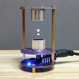 Ultrahang felfüggesztő elektronikus DIY gyártó részecskék hullámforrasztó képzési DIY készlet Tudományos kísérletek
US$16.09
US$13.99
View It
Ultrahang felfüggesztő elektronikus DIY gyártó részecskék hullámforrasztó képzési DIY készlet Tudományos kísérletek
US$16.09
US$13.99
View It


hjlc Did you maga to make it work? Mine appears to have no program in the microprocessor. Did you loaded a program into it?
Válasz 24/09/2022
hjlc Assembled, all connectins checked. No 40khz signal out of the STC. It looks like us not programmed. I asked to support and they told me they have no program.
Válasz 24/09/2022
hjlc No programming needed?
Válasz 24/09/2022
zzzackk thx so much for explaining the schematics to us!!
Válasz 23/01/2023
BG252512551 MayI have the mounting layout?
Válasz 20/04/2023| Cégünk | Lépjen kapcsolatba velünk | Fizetés és szállítás | Partnerségi programok |
|---|---|---|---|